AT1032S
The Ultimate General-Purpose Test Platform with 32 I/Os, Programmable Power, and Full Communication Support
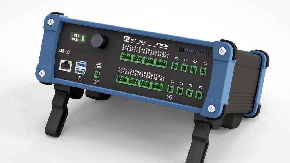
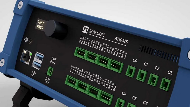
The AT1032S Test Sequencer is a comprehensive automated test equipment solution designed for functional PCBA testing, system validation, and firmware verification. With 32 programmable analog/digital I/Os, 8 dry contact relays, programmable power supply, and extensive communication interfaces (USB, CAN, Ethernet, RS232, RS485, I2C, SPI, UART), the AT1032S eliminates the need for building custom test fixtures from scratch. It connects to a computer (Windows, Linux, MacOS) via USB or Ethernet and is controlled through comprehensive APIs supporting Python and NodeJS.

- 32 Programmable I/Os
- 8 Dry Contact Relays
- Programmable Power Supply (0-13V, 2A)
- USB, CAN, RS232, I2C, SPI, UART
- Daisy-chain multiple units
Applications
- Functional PCB Testing:
Automate comprehensive testing of assembled PCBs - Semiconductor Validation:
Accelerate validation of ICs with programmable signal generation and capture - Communication Protocol Validation:
Test USB, CAN, RS232, I2C, SPI, UART interfaces - Power Supply Testing:
Validate power management circuits and battery chargers - System Integration Validation:
Validate complete systems with multiple subsystems - Firmware functional testing:
Automate firmware verification after flashing
Benefits
- All-in-One Solution:
Combines multiple test functions in a single device - API-First Design:
Easy integration with Python, NodeJS, and C - Flexible I/O Configuration:
Adaptable to a wide range of testing scenarios - Scalable Architecture:
Daisy-chain multiple units for expanded capabilities - Precise Measurements:
High-resolution current sensing on key outputs - Stand-alone or Remote Operation:
Run tests with or without a PC connection
| Modell | Bezeichnung | Preis (€) zuzügl. MwSt | Preis (€) inkl. MwSt |
|---|---|---|---|
AT1023 Test Sequencer|
| | ||
| AT1032S | Test Sequencer mit 32 I/Os, prog. Stromversorgung, Communication Support | 2.900,00 € | 3.451,00 € |
| Preise Stand 2026-03-01 - Preisirrtum vorbehalten - Es gelten die Preise aus unseren Angeboten | |||
Key Features at a Glance
Hardware Capabilities:
32 Programmable I/Os (±25V input, 0-24V output)
8 Dry Contact Relays (up to 60V, 2A)
Programmable Power Supply (0-13V, 2A)
2 USB 3.0 Ports with power cycling and current measurement
3 Ethernet Ports (100BASE-T)
Communication Interfaces: CAN, RS232, RS485, I2C, SPI, UART
Built-in HMI: LCD display, rotary encoder, speaker
Software & Control:
Python, NodeJS and C APIs for test automation
Stand-alone mode – runs test sequences without PC connection
Remote mode – controlled from your computer
Synchronization via SYNC IN/OUT for multi-device setups
Current measurement on power supply, USB ports, and relay number 4
Cross-platform support: Windows, Linux, MacOS
Power Supply:
Power supply voltage 25V DC ± 0.5V
Power supply current 3A max
Connector type Barrel jack (5.5/2.1mm)
General Purpose I/O Specifications:
Digital I/O:
Number of I/Os: 32 programmable channels
Input voltage range: -25V to +25V
Output voltage range: 0V to +24V
Configurable thresholds: VIH and VIL programmable per channel
Output levels: VOH and VOL programmable per channel
Input impedance: 1 MΩ typical
Output current: 25 mA max per channel
Analog Input:
Resolution: 12-bit ADC
Input voltage range: -25V to +25V
Accuracy: ±25 mV typical
Supported Protocols on Select I/Os:
I2C: Master modes, up to 400 kHz (slave mode currently not supported)
SPI: Master mode, up to 10 MHz (slave mode currently not supported)
UART: Baud rates from 300 to 1 Mbps
Programmable Power Supply:
Output voltage range: 0 to 13V, programmable
Output current: 2A max
Voltage accuracy: ±100 mV
Current measurement range: 0 to 2A
Current measurement resolution: 1.5 mA
Current measurement accuracy: ±3 mA typical
Over-current protection: Yes, fixed 2A limit
PCB Functional Testing
End-of-Line Testing
Automate comprehensive testing of assembled PCBs before they leave your production line. The AT1032S can validate digital circuits, analog signals, communication interfaces, and power consumption in a single test sequence.
Typical Test Scenarios:
Verify proper voltage rails across the board
Test digital I/O functionality at various logic levels (1.0V, 1.8V, 3.3V, 5V, even 24V logic level).
Stimulate the circuit with specific voltage patterns
Validate analog sensor outputs
Check I2C/SPI device responses
Measure quiescent and active current consumption
Benefits:
Reduce test time from minutes or hours to seconds
Eliminate human error with automated scripts
Generate detailed test reports automatically and/or feed test results to your dashboard
Achieve 100% test coverage consistency
Bring-Up and Debug
When debugging a new PCB design, the AT1032S serves as a powerful multi-function tool that combines the capabilities of multiple instruments.
Use Cases:
Apply controlled power while monitoring current draw
Stimulate inputs and observe outputs in real-time
Inject test patterns via communication buses
Isolate faulty sections using relay-controlled signal routing
Log long-term behavior (voltages, currents, communication responses)for intermittent issue detection
Bed-of-Nails Testing
The AT1032S can serve as the controller for custom bed-of-nails test fixtures.
Advantages:
32 I/Os provide comprehensive coverage
Relay-switched test points for routing flexibility
Built-in current measurement for short detection
Programmable power supply for device under test
Capabilities:
Coordinate probe positioning (via external motion controllers)
Perform measurements at designated test points
Generate test reports with spatial information
Adapt to different board designs quickly
System Integration Testing
Multi-Board System Validation
For systems consisting of multiple interconnected PCBs, the AT1032S can orchestrate complex test sequences that validate inter-board communication and system-level functionality.
Example Scenarios:
Test communication between main controller and peripheral boards
Simulate external sensors and actuators
Verify system response to various input conditions
Validate power sequencing across multiple boards
Monitor system behavior under different load conditions
Advanced Features:
Daisy-chain multiple AT1032S units for expanded I/O coverage
Synchronize actions across devices for precise timing
Integrate with external equipment (oscilloscopes, spectrum analyzers) via scripting
Production Line Integration
The AT1032S integrates seamlessly into automated production lines, communicating with other equipment and factory systems.
Integration Points:
Connect to MES (Manufacturing Execution Systems) via Ethernet
Trigger test sequences based on external signals (barcode scanners, PLCs)
Report test results to databases in real-time
Control upstream/downstream equipment via dry contact relays
Implement pass/fail routing with visual and audible indicators
Communication Protocol Testing
Multi-Protocol Validation
With support for CAN, RS232, RS485, I2C, SPI, UART, and Ethernet, the AT1032S can validate complex communication scenarios.
Test Scenarios:
CAN Bus Testing
Verify CAN message transmission and reception
Test node addressing and filtering
Validate error handling and recovery
Monitor bus loading and timing
RS485 Multi-Drop Networks
Test communication with multiple slave devices
Verify collision detection and resolution
Validate long-distance communication
Check termination and biasing
I2C/SPI Device Communication
Scan for I2C devices on the bus
Read/write to specific registers
Verify data integrity
Test clock stretching and multi-master scenarios
Protocol Conformance Testing
Ensure your device’s communication implementation meets protocol specifications.
Testing Capabilities:
Generate edge cases and error conditions
Verify timing requirements
Test error recovery mechanisms
Validate protocol state machines
Environmental and Stress Testing
Temperature and Environmental Testing
Use the AT1032S to automate testing across different environmental conditions when paired with environmental chambers.
Test Scenarios:
Monitor device behavior across temperature ranges
Validate operation under humidity variations
Test power consumption at temperature extremes
Verify communication reliability in harsh conditions
Burn-In and Life Testing
Perform extended reliability testing with automated monitoring and logging.
Features:
Run devices for extended periods (hours to days)
Log all parameters continuously
Detect and flag anomalies automatically
Generate detailed life-test reports
Getting Started with Your Application
Not sure if the AT1032S fits your application? Contact our technical team to discuss your specific requirements. We can help you:
Design custom test sequences
Create interface cables and adapters
Integrate with your existing test infrastructure
Provide training and support
-
- Geräte
-
Modell Bezeichnung Preis (€)
zuzügl. MwStPreis (€)
inkl. MwStAT1023 Test Sequencer AT1032S Test Sequencer mit 32 I/Os, prog. Stromversorgung, Communication Support 2.900,00 € 3.451,00 € Preise Stand 2026-03-01 - Preisirrtum vorbehalten - Es gelten die Preise aus unseren Angeboten - Spezifications
-
Key Features at a Glance
Hardware Capabilities:
32 Programmable I/Os (±25V input, 0-24V output)
8 Dry Contact Relays (up to 60V, 2A)
Programmable Power Supply (0-13V, 2A)
2 USB 3.0 Ports with power cycling and current measurement
3 Ethernet Ports (100BASE-T)
Communication Interfaces: CAN, RS232, RS485, I2C, SPI, UART
Built-in HMI: LCD display, rotary encoder, speakerSoftware & Control:
Python, NodeJS and C APIs for test automation
Stand-alone mode – runs test sequences without PC connection
Remote mode – controlled from your computer
Synchronization via SYNC IN/OUT for multi-device setups
Current measurement on power supply, USB ports, and relay number 4
Cross-platform support: Windows, Linux, MacOSPower Supply:
Power supply voltage 25V DC ± 0.5V
Power supply current 3A max
Connector type Barrel jack (5.5/2.1mm)General Purpose I/O Specifications:
Digital I/O:
Number of I/Os: 32 programmable channels
Input voltage range: -25V to +25V
Output voltage range: 0V to +24V
Configurable thresholds: VIH and VIL programmable per channel
Output levels: VOH and VOL programmable per channel
Input impedance: 1 MΩ typical
Output current: 25 mA max per channelAnalog Input:
Resolution: 12-bit ADC
Input voltage range: -25V to +25V
Accuracy: ±25 mV typicalSupported Protocols on Select I/Os:
I2C: Master modes, up to 400 kHz (slave mode currently not supported)
SPI: Master mode, up to 10 MHz (slave mode currently not supported)
UART: Baud rates from 300 to 1 MbpsProgrammable Power Supply:
Output voltage range: 0 to 13V, programmable
Output current: 2A max
Voltage accuracy: ±100 mV
Current measurement range: 0 to 2A
Current measurement resolution: 1.5 mA
Current measurement accuracy: ±3 mA typical
Over-current protection: Yes, fixed 2A limit - Applications
-
PCB Functional Testing
End-of-Line Testing
Automate comprehensive testing of assembled PCBs before they leave your production line. The AT1032S can validate digital circuits, analog signals, communication interfaces, and power consumption in a single test sequence.
Typical Test Scenarios:
Verify proper voltage rails across the board
Test digital I/O functionality at various logic levels (1.0V, 1.8V, 3.3V, 5V, even 24V logic level).
Stimulate the circuit with specific voltage patterns
Validate analog sensor outputs
Check I2C/SPI device responses
Measure quiescent and active current consumptionBenefits:
Reduce test time from minutes or hours to seconds
Eliminate human error with automated scripts
Generate detailed test reports automatically and/or feed test results to your dashboard
Achieve 100% test coverage consistencyBring-Up and Debug
When debugging a new PCB design, the AT1032S serves as a powerful multi-function tool that combines the capabilities of multiple instruments.
Use Cases:
Apply controlled power while monitoring current draw
Stimulate inputs and observe outputs in real-time
Inject test patterns via communication buses
Isolate faulty sections using relay-controlled signal routing
Log long-term behavior (voltages, currents, communication responses)for intermittent issue detectionBed-of-Nails Testing
The AT1032S can serve as the controller for custom bed-of-nails test fixtures.
Advantages:
32 I/Os provide comprehensive coverage
Relay-switched test points for routing flexibility
Built-in current measurement for short detection
Programmable power supply for device under testCapabilities:
Coordinate probe positioning (via external motion controllers)
Perform measurements at designated test points
Generate test reports with spatial information
Adapt to different board designs quicklySystem Integration Testing
Multi-Board System Validation
For systems consisting of multiple interconnected PCBs, the AT1032S can orchestrate complex test sequences that validate inter-board communication and system-level functionality.
Example Scenarios:
Test communication between main controller and peripheral boards
Simulate external sensors and actuators
Verify system response to various input conditions
Validate power sequencing across multiple boards
Monitor system behavior under different load conditionsAdvanced Features:
Daisy-chain multiple AT1032S units for expanded I/O coverage
Synchronize actions across devices for precise timing
Integrate with external equipment (oscilloscopes, spectrum analyzers) via scriptingProduction Line Integration
The AT1032S integrates seamlessly into automated production lines, communicating with other equipment and factory systems.
Integration Points:
Connect to MES (Manufacturing Execution Systems) via Ethernet
Trigger test sequences based on external signals (barcode scanners, PLCs)
Report test results to databases in real-time
Control upstream/downstream equipment via dry contact relays
Implement pass/fail routing with visual and audible indicatorsCommunication Protocol Testing
Multi-Protocol Validation
With support for CAN, RS232, RS485, I2C, SPI, UART, and Ethernet, the AT1032S can validate complex communication scenarios.
Test Scenarios:
CAN Bus Testing
Verify CAN message transmission and reception
Test node addressing and filtering
Validate error handling and recovery
Monitor bus loading and timingRS485 Multi-Drop Networks
Test communication with multiple slave devices
Verify collision detection and resolution
Validate long-distance communication
Check termination and biasingI2C/SPI Device Communication
Scan for I2C devices on the bus
Read/write to specific registers
Verify data integrity
Test clock stretching and multi-master scenariosProtocol Conformance Testing
Ensure your device’s communication implementation meets protocol specifications.
Testing Capabilities:
Generate edge cases and error conditions
Verify timing requirements
Test error recovery mechanisms
Validate protocol state machinesEnvironmental and Stress Testing
Temperature and Environmental Testing
Use the AT1032S to automate testing across different environmental conditions when paired with environmental chambers.
Test Scenarios:
Monitor device behavior across temperature ranges
Validate operation under humidity variations
Test power consumption at temperature extremes
Verify communication reliability in harsh conditionsBurn-In and Life Testing
Perform extended reliability testing with automated monitoring and logging.
Features:
Run devices for extended periods (hours to days)
Log all parameters continuously
Detect and flag anomalies automatically
Generate detailed life-test reportsGetting Started with Your Application
Not sure if the AT1032S fits your application? Contact our technical team to discuss your specific requirements. We can help you:
Design custom test sequences
Create interface cables and adapters
Integrate with your existing test infrastructure
Provide training and support
Features & Options
32 programmable I/Os for both analog and digital signals
with ±25V range
Each of the 32 I/O pins can be configured as digital input/output or analog input, supporting voltage ranges from -25V to +25V for inputs and 0 to 24V for outputs. Configurable threshold levels (VIH/VIL) and output levels (VOH/VOL) make the AT1032S adaptable to virtually any testing scenario, from ultra low 1.0V logic to 24V industrial systems.
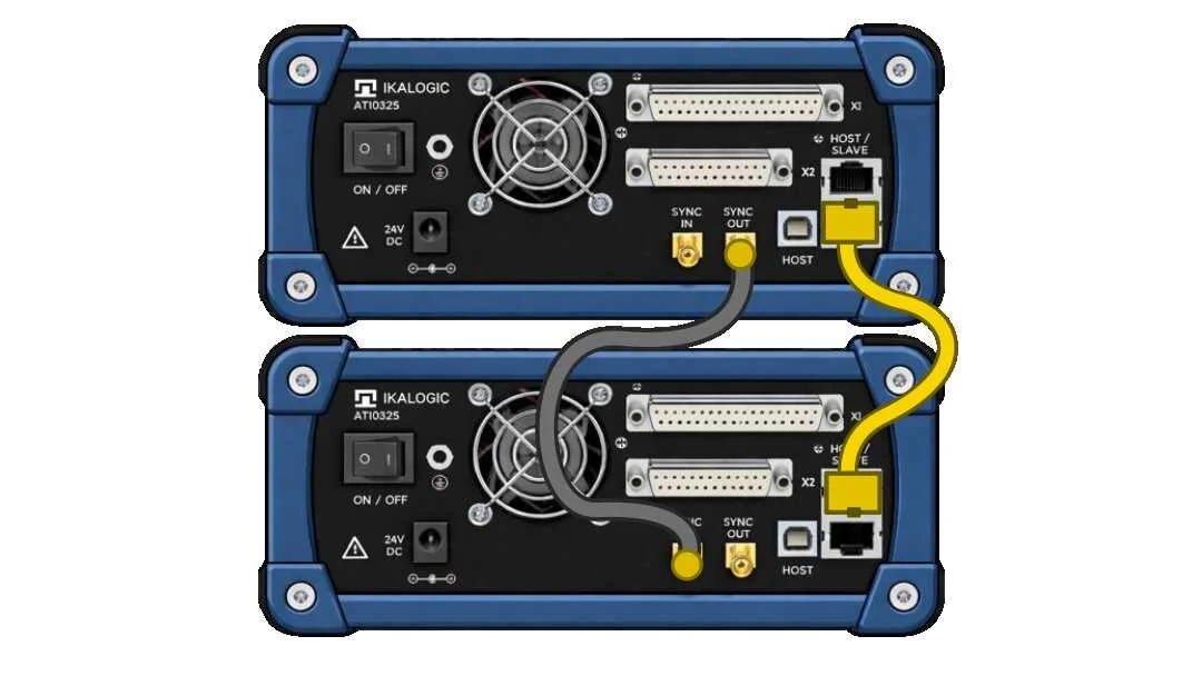
Scale your test system by daisy-chaining multiple AT1032S units
Need more I/Os? No problem. The AT1032S features SYNC IN and SYNC OUT ports that allow multiple units to be daisy-chained together, expanding your test system as your requirements grow. The API transparently handles multiple devices, making it easy to control hundreds of I/Os from a single test script.
Sales and distribution
Allice Messtechnik GmbH, based in Frankfurt, has been an Ikalogic sales partner for many years.
Allice provides technical support and services for Ikalogic devices.
Request a quote based on current conditions – or simply call a measurement technology specialist.